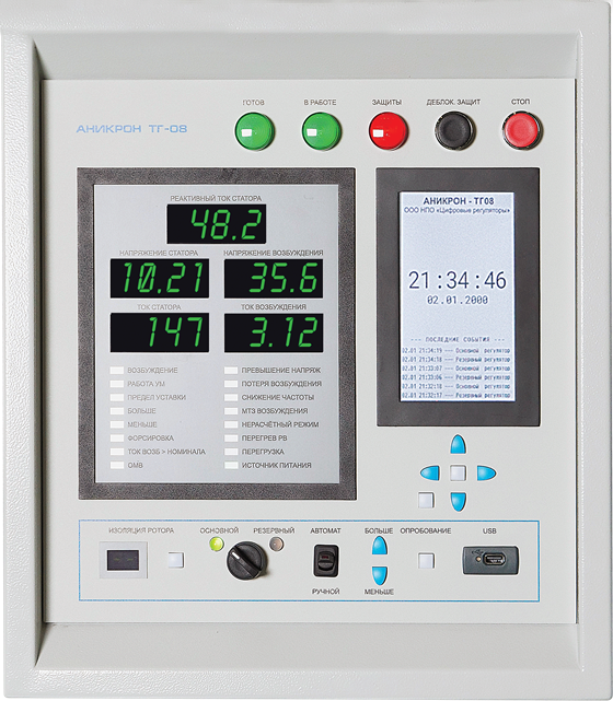
ANIKRON TG-08
Digital excitation regulator ANIKRON TG-08 has been designed to automatically supply rectified current to the field winding of a static synchronous generator.
Main characteristics:
-
Swiching to working mode with precision synchronization method;

- Swiching to working mode with self-synchronization method (if necessary);
- Voltage frequency adjustment and high-power circuit breaker initiation;
- Excitation voltage boosting of given factor (at least 2) in case of the grid disturbances causing voltage reduction in a power-station bus system;
- Reactive power deloading;
- Active power deloading;
- Precise generator voltage control not less than ±0,2 % of a given DC performance;
- Stable operation in transient and emergency modes (load surges and rejections, short circuits);
- Bumpless switching between the main and reserve control units if the main unit fails without changing a generator mode;
- Remote AEC setting;
- Generator voltage deviation and derivative / generator voltage frequency deviation and derivative/ generator excitation current derivative algorithms for generator excitation current regulation;
- Time-dependent excitation current overload protection;
- De-excitation in case of the grid disturbances causing voltage increase in a power-station bus system;
- Underexcitation mode;
- Limiting of consumed reactive power;
- Field suppression in emergency modes;
- Electrical braking of a hydraulic power pack (upon customer request);
- Sensor LCD to display oscillograms and service information;
- Synchronization with an external time source;
- Event log with extended recording capacity.

Protection algorithms:
- Rotor overload protection;
- Short-circuit protection of rectified voltage circuits;
- Overcurrent protection;
- Stator voltage -rise protection in idling mode;
- Phase asymmetry protection;
- Protection from power-pack (thyristor bridge/PA) failures and internal faults;
- Rotor/exciter overheat protection;
- Protection from failed initial excitation;
- Protection from the failure of both regulation channels;
- Control and monitoring of main excitation system units.
| Parameter | Unit | Value |
| Rated excitation voltage, max. | V | 300 |
| Rated excitation current, max | А | 400 |
| Max. steady-state voltage | V | 600 |
| Max. steady-state current | А | 700 |
| Voltage boosting ratio | r.u. | 2 |
| Current boosting ratio | r.u. | 2 |
| Excitation boost time | s | max. 60 |
| Excitation deboost time | ms | max. 150 |
| Excitation system response time while boosting | ms | 60 |
| Excitation current stabilization accuracy | % | ±1 |
| Working frequency range | Hz | 45-65 |
| Response time to disturbance | ms | 20 |
| Generator bus system current control accuracy relative to a given static value | % | 0,2 |
| Network protocols and communication interfaces | Modbus, Ethernet, Profibus, 4-20mA current loop | |
| Excitation control system power supply | 220V/380V/Battery |
